|
|
| |
Displacement measurement
- The basic principle of displacement measurement
- LVDT construction
- LVDT application
|
1. The basic principle of displacement measurement
|
| |
The displacement measurement (move, shift, slip) like each other physical quantity measurement
is its mapping to other measureable physical quantity mostly electrical voltage or current.
The LVDTs made by Peltron measure linear displacement by converting it directly or indirectly to
voltages: ± 10V, ± 5V, 0÷10V, or current 4÷20mA. As it was said there are two main methods
of displacement measurement or in other words two groups of LVDTs made by Peltron:
▪ indirect converting - for transducers series AC/AC
▪ direct converting - for transducers series DC/DC)
The indirect method is based on cooperation of the transducers with an additional
conditioning device which converts the transducer's output signal (amplitude modulated 5kHz or
1kHz frequency) to ± 10V, ± 5V, 0÷10V, or current 4÷20mA.
The direct method however, lies in the converting from displacement
to voltage ±10V lub ±5V without any additional conditioning device.
The output signal from the transducer or conditioning device is mostly further converted to
digital signal in a specified protocol than recorded and displayed.
Peltron supplies its customers with transducers, conditioning devices also analog/digital converters and software.
|
|
2. LVDT construction.
|
a. Principle of working
|
| |
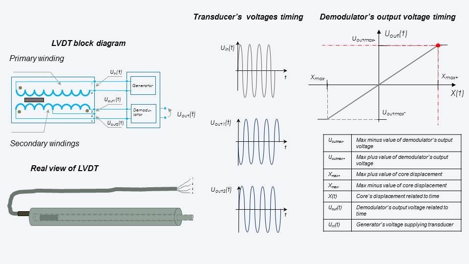
The basic item of all transducers is a differential transformer.
It consists of a primary winding and two secondary windings which are symetricaly wound
to the primary, all of them are wound around the transfomer's core.
There is a moveable magnectic core inside the transformer's core. The primary winding is excited
by AC current mostly 5kHz (for PLx 1kHz). There are two voltages induced in the secondary windings
different in magnitude (except balanced state) and in the opposite phase. When the moveable magnetic
core is in the middle position, the output voltage ( which is the sum of both secondary windings' voltages)
should be equal zero and the transformer is balanced. If the moveable magnetic core is out of the balanced
state, the output voltage's magnitude is not equal zero and straight proportional (linear )to the
magnetic core's position. The output voltage's phase changes in the time of zero crossing.
The moveable magnetic core has no connection with the transducer's body so it results
in no possibilty to wear. No friction feature results in long term work. The transducer has no
histeresis error and its strength, reliability, and repeatabily is very high indeed.
|
|
 |
b. Division of LVDTs.
|
| |
LVDTs made by Peltron can be divided into two main groups:
AC/AC - transducers which constitute this group contain only a differential transformer inside.
There are following:
PTx, PJx, PKx, PSx, PSy, PTs, PJs, PLx.
For proper working od these types an additional device is needed which perform function of generator and demodulator, there
are following:
▪ one channel - WG06, WG07, MPL701,
▪ multichannel - MPL508, MPL408 and others.
DC/DC - transducers which constitute this group beside a differential transformer contain
embeded generator and demodulator inside, there are following:
PIz, PSz, PJy,PSe. To ensure proper working of this group only DC voltage is required.
Beside the above division following are also possible:
▪ with return spring - PSx, PSy, PSz
▪ electrical connector fit to enclosure - PJs, PSx (optional).
▪ miniature - PTs, PIz2,5
▪ easy accessible electronics - PJy
▪ high temperature (up to 200°C )- PSx, other AC/AC to agree
|
|
c. Ranges.
|
| |
|
LVDTs made by Peltron designed to measure displacement within scope 1÷3000 mm.
Standard ranges are following:
|
| No | Range [mm] | Type |
| 1 | 1 | PSx1 |
| 2 | 2 | PSx2,PSy2 |
| 3 | 2,5 | PIz2,5 |
| 4 | 5 | PSy5,PTs5,PSz5 |
| 5 | 6 | PSx6,PTx6 |
| 6 | 10 | PTx10,PSx10,PSy10 |
| 7 | 20 | PTx20,PJx20,PSx20,PIz20,PJy20,PSz20 |
| 8 | 30 | PTx30,PJx30,PSx30,PJy30 |
| 9 | 50 | PTx50,PJx50,PJs50,PKx50,PSx50,PSy50,PIz50,PJy50,PSz50 |
| 10 | 100 | PTx100,PJs100,PKx100,PSx100,PIz100,PJy100,PSz100 |
| 11 | 150 | PJx150,PSx150,PIz150 |
| 12 | 200 | PTx200,PJx200,PJs200,PKx200,PSx200,PJy200 |
| 13 | 210 | PJy210 |
| 14 | 250 | PJy250 |
| 15 | 300 | PJx300,PIz300,PJy300 |
| 16 | 500 | PJx500,PJs500,PLx500 |
| 17 | 1000 | PLx1000 |
| 18 | 1500 | PLx1500 |
| 19 | 2000 | PLx2000 |
| 20 | 3000 | PLx3000 |
|
|
|
d. Accuracy of LVDTs.
|
| |
Only one error is important for LVDTs it is linearity error.
Considering transducers made by Peltron three errors have to be mentioned:
▪ For AC/AC transducers: 0,5% MR, 0,25%MR, 0,1%MR, it is calculated from output signal
to displacemenet characteristic (output signal is demodulated 5kH or 1 kHz sin wave ).
▪ For DC/DC transducers: 0,5% MR and 0,25% MR it is calculated from output signal
to displacemenet characteristic (output signal is DC voltage or DC current).
|
|
3. LVDT application.
|
LVDTs are widely used in applications where is need to measure not only displacement, move, shift or split
but also quantities which can be calculated from above, like: pressure, force or stress.
Sophisticated applications take place in harsh conditions areas: vibrations, heat, rain, snow, sand, moisture.
Here are examples of such applications:
|
| ▪ | diagnostic of machines and devices |
| ▪ | servomotors' piston movement monitoring |
| ▪ | concrete beam bending measurement |
| ▪ | concrete walls dilatation monitoring |
| ▪ | coal layer thicknes monitoring in coal boilers |
| ▪ | bridge, ceiling and viaduct loading test measurement |
| ▪ | wide area roof safety monitoring |
| ▪ | car suspension spring testing |
| ▪ | ship collisions testing |
| ▪ | trapezium screw shift monitoring |
| ▪ | spring and framework susceptibility testing |
| ▪ | plant speed growing monitoring |
| ▪ | bulkhead testing |
| ▪ | railways testing |
| ▪ | turbine driver testing |
|
|
|
|
|
|
|
|
|
|

 Home
Home
)
)
)
)
)
)
)
)
)
)
)
)
)
)
)
)
)
)
)
)
)
